Start-Up/Maintenance
This section will describe the basic steps and procedures that must be followed to ensure a safe start up when starting up the PowerPanel for the first time or restarting the system after a fuel shutdown or power outage event.
Initial Start-Up/Commissioning
The PowerPanel is a 120VAC based system. Only qualified personnel familiar with all functions of a fueling forecourt are to perform a start or restart operation.
Initial Start-Up/Commissioning Procedure
- Verify that all circuit breakers in the fueling panelboard are in the off position and verify that the ‘CP’ control breakers on the FCP-1 panel is off, as well.
- Verify that all wires are secure and that all trash from the installation has been removed. In particular, scraps of wire and/or insulation must be removed to prevent the shorting out of any components.
- After making sure all personnel are clear of the equipment, locate and turn on the circuit breaker in the panelboard labeled as E-STOP/FUEL PANEL POWER to the ON position.
- After verifying with a meter that 120V is present at terminals ‘L’ and ‘N’, turn the 10A CP breaker on the panel marked “Control Power” and turn it to the ON position.
- With a voltmeter set to VAC, measure the voltage at ES1, ES2, ES3 to neutral.
- Result: If all Fuel Shutdown pushbuttons are in the operating position, the reading of 120V should be present at all “ESx” terminals. Verify the 24VDC Power Supply is ON.
- If 120VAC is present on ES1 only, check the wiring of the Cashier Control Shutdown button and make sure that it is correct. If necessary, open the Cashier Control enclosure to troubleshoot. The bottom wire of ES2 will be landed on the shutdown button’s terminal that is furthest away from the reset button. The wire of the shutdown closest to the reset will land on the top terminal of ES3. If this is not the case, please check all ground and neutral bonding jumpers to make sure that connections are solid.
- At this point, press the RESET button on either the front door of the PowerFlow panel or the remote reset if wired in.
- Result: The ES1 & ES2 contactors should energize at this point and all STP contactors will pull in as well.
- With your meter, measure the terminals marked “2” and “N1” located at either the top right or top left of the panel. The voltmeter reading should be 120VAC.
- Turn on the 3-pole or 2-pole breakers designated for VFC STP motors. Measure each STP contactor to verify that all phases are present for each drive.
- You can now perform line leak detection, if necessary, prior to powering on the dispensers.
- Turn each dispenser breaker to the ON position. Measure the voltage at the dispenser power terminals after each breaker is switched.
- Verify after turning on each dispenser breaker that its associated low voltage relays, and Ethernet module are energized. (Low Voltage section).
- With the system up and running, go to each Fuel Shutdown button and simulate an emergency fuel shutdown.
- If your remote shutdown buttons are of the “Break Glass” type, carefully unscrew the cover until the button releases.
- After each time the panel shuts down, press the RESET button until all Shutdown stations have been tested.
- If your system uses a TLM that has an input/output card (Veeder Root), verify that the program will only send an output as long as the line leak detector is operational.
The initial start-up/commissioning is now complete.
Restarting System from Power Failure
In the event of a power failure, the ES1 & ES2 contactors will drop out immediately.
Restarting System Procedure
- Verify that no damage from a lightning strike or other storm-related damage has occurred.
- If all facility equipment checks out okay, press the green “RESET” button to start fueling operations again.
Shutting Down a Dispenser for Maintenance
If it is necessary to shut down a single dispenser for maintenance, please follow the lockout procedure located in chapter 3, section 2 at the end of the chapter for a safe shutdown.
- Bag the dispenser according to site protocols.
- Locate the breaker in the panelboard for that dispenser and turn it to the OFF position.
- Perform the lockout procedure.
Lockout Procedure
Electrical contractors or anyone qualified to work on the PowerPanel must be familiar with proper lockout procedures.
The breakers for this panel are capable of being locked out during maintenance operations or, if otherwise required, of being locked in the ON position.
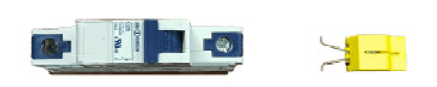
FIG 1 TYPICAL CIRCUIT BREAKER AND BREAKER LOCKOUT/LOCKON ADAPTER
Critical or life safety loads require the power source to be locked in the ON position so there will be no accidental disruption of service.
Procedure
The following is the typical procedure for locking out a breaker.
STEP 1: Turn designated breaker to the OFF position.
STEP 2: With your thumb and forefinger, squeeze the retainer clips of the lockout together. Locate the two retainer holes just below the breaker handle.
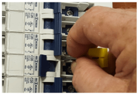
FIG 2 – APPLYING LOCKOUT
STEP 3: Slip the retainer pins into the two holes and release.
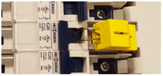
FIG 2 STEP 3 – LOCKOUT ATTACHED
STEP 4: Now raise the tab of the lockout and push down toward the retaining clips. The body will slide down over the clips, and the lockout loop will appear near the top.
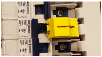
FIG 2 STEP 4 – LOCKOUT IN PLACE
STEP 5: With the lockout loop exposed, apply your padlock lock to the device. The lockout will take a lock with approximately a 5/16” shank. If you have a TAG-OUT procedure in place, apply notice at this time.
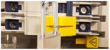
FIG 2 STEP 5 – BREAKER LOCKED OUT
If you are unsure or have questions regarding this or any other procedure described in this manual, please contact your local representative.
Other Lockouts
The main breaker that feeds power to the PowerPanel will need to be locked out if servicing of the panel itself is required.
Consult the breaker manufacturer’s procedure to perform the lockout.
If you have the optional STP breaker and bus assembly as part of your unit, use the lockout procedure as listed in 2.3. The lockouts will be different since they are made to accommodate 2 or 3 pole breakers.
Again, with this optional assembly there will be a separate feed breaker powering the bus assembly. Consult the manufacturer’s recommendations in regard to the proper method for locking out the breaker.
Maintenance
The PowerPanel needs very little maintenance to keep it in good working order.
Monthly:
- Perform an Emergency Fuel Shutdown and Reset operation and verify proper operation. If you have more than one shutdown, make sure each shutdown will turn the system to the off position.
- Open the Fueling Panel section and inner door. Visually inspect the operational lights on the TVSS to verify that it is in operational mode.
- For NEMA 3R enclosures, verify that the 3-point door latches are adjusted properly. When adjusted properly, the enclosure door will compress about half of the door gasket all the way around.
Semi-Annually:
- Inspect all door gaskets for any damage and if found, replace immediately.
- Inspect interior of cabinets (Both LV Section & Fuel Panel sections) for any buildup of moisture or other aggregates. Clean as required.
- Check the incoming voltage at the panelboard main breaker for all 3 phases and neutral.
Annually:
- Power down the main breaker of the panelboard and go through the wiring connections to verify that all is tightened as should be. Perform random ‘pull’ tests on some of the wiring to verify that no loose wiring exists.
