Safety & Startup/Maintenance
Table of Contents
Safety…………………………………………………………………………………………………………………………………………….2
Safety Regulations and Code Requirements (2.1)……………………………………………………………….2
UL (Underwriters Laboratories) Standards listed under NFPA 30A and 508A………………….2
NEC 514.11…………………………………………………………………………………………………………………………………..2
NEC 514.13…………………………………………………………………………………………………………………………………..3
Warning Label Descriptions (2.2)…………………………………………………………………………………………..3
Note/Notice…………………………………………………………………………………………………………………………………4
Caution…………………………………………………………………………………………………………………………………………4
Warning………………………………………………………………………………………………………………………………………..5
Danger………………………………………………………………………………………………………………………………………….5
Other Labels……………………………………………………………………………………………………………………………….6
Lockout………………………………………………………………………………………………………………………………………..6
High Voltage……………………………………………………………………………………………………………………………….6
Installation and Start Up…………………………………………………………………………………………………………6
Installation of PowerPanel Integrated Systems…………………………………………………………………7
Site Template……………………………………………………………………………………………………………………………..7
Equipment Delivery and Acceptance…………………………………………………………………………………….7
Setting Up the Equipment………………………………………………………………………………………………………7
Wiring Connections………………………………………………………………………………………………………………..8
Cashier Control Center – Optional …………………………………………………………………………….8
Remote Shutdown…………………………………………………………………………………………………………………10
Start-Up/Maintenance………………………………………………………………………………………………………….10
Initial Start-Up Commissioning………………………………………………………………………………………….10
Initial Start-Up/Commissioning Procedure……………………………………………………………………….10
Restarting System from Power Failure……………………………………………………………………………..12
Restarting System Procedure……………………………………………………………………………………………….12
Shutting Down a Dispenser for Maintenance…………………………………………………………………..12
Lockout Procedure…………………………………………………………………………………………………….12
Procedure………………………………………………………………………………………………………………………………..13
Other Lockouts………………………………………………………………………………………………………………………15
Maintenance…………………………………………………………………………………………………………………………..15
Monthly……………………………………………………………………………………………………………………………………15
Semi-Annually………………………………………………………………………………………………………………………..15
Annually…………………………………………………………………………………………………………………………………..16
Safety
This section will describe the various warning labels and their levels of importance as related to installation, startup and maintenance.
This system is 120VAC control, and with the UL489 bus system, all dispenser breakers are on the same phase. The maximum potential of the panel is 120VAC.
2.1 Regulations and Code Requirements
When providing any equipment that includes product dispensing controls as an integrated component, the equipment must meet the following standards:
UL (Underwriters Laboratories) Standards listed under NFPA 30A and 508A
NEC 514.11:
Fuel dispensing systems shall be provided with one or more clearly identified emergency shutoff devices or electrical disconnects. Such devices or disconnects shall be installed in approved locations but not less than 6m (20ft) or more than 30m (100ft) from the fuel dispensing devices that they serve. Such devices or disconnects shall be installed in approved locations but not less than 6m (20ft) or more than 30m (100ft) from the fuel dispensing devices that they serve.
Emergency shutoff devices or electrical disconnects shall disconnect power to all dispensing devices; to all remote pumps serving the dispensing devices; to all associated power, control, and signal circuits; and to all other electrical equipment in the hazardous (classified) locations surrounding the fuel dispensing devices and shall mechanically or electrically isolate other fluid transfer systems serving the fuel dispensing area.
When more than one emergency shutoff device or electrical disconnect is provided, all devices shall be interconnected. Resetting from an emergency shutoff condition shall require manual intervention and the manner or resetting shall be approved by the authority having jurisdiction. At attended motor fuel dispensing facilities, the devices or disconnects shall be readily accessible to the attendant and labeled with an approved sign stating “EMERGENCY FUEL SHUTOFF” or equivalent language.
At unattended motor fuel dispensing facilities, the devices or disconnects shall be readily accessible to patrons and at least one additional device or disconnect shall be readily accessible to each group of dispensing devices on an individual island. The device(s) or disconnect(s) shall be labeled with an approved sign stating “EMERGENCY FUEL SHUTOFF” or equivalent language.
NEC 514.13:
Each dispensing device shall be provided with a means to remove all external voltage sources, including power, communications, data, and video circuits and including feedback, during periods of maintenance and service of the dispensing equipment. The location of this means shall be permitted to be other than inside or adjacent to the dispensing device. The means shall be capable of being locked in the open position. The provision for locking or adding a lock to the disconnecting means shall be installed on or at the switch, circuit breaker or other device used as the disconnecting means and shall remain in place with or without the lock installed.
2.2 Warning Label Descriptions
There are 4 levels of warning labels used. This modified description is from ANSI Z535.
1. NOTE/NOTICE

FIG 2.2-1 TYPICAL NOTE LABELS
- This type of label is used to point out important information that a technician or operator needs to be aware of. Labels are usually blue and white but can also be composed of text with the triangle “alert” icon.
2. CAUTION

FIG 2.2-2 CAUTION LABEL
- This label is displayed with cautionary information which indicates that minor injury and potential equipment damage may result if instructions are not followed. Coloration is usually yellow with black or red lettering.
3. WARNING


FIG 2.2-3 WARNING LABEL
- This level notice will be displayed when serious injury may occur if the instructions are not strictly followed. These warnings typically appear when working around live equipment with moving machinery. The label is orange and black in color.
4. DANGER

FIG 2.2-4 DANGER LABELS
- This is the highest level of warning; if the instructions are not followed, serious injury and even death may occur. The DANGER logo uses a red or black and red background with white lettering.
2.2.1 Other Labels
There are also some precautionary labels that may be used in this manual.
LOCKOUT

FIG 2.2.1-1 LOCKOUT LABEL
- Recommendation to the qualified person that Lockout/Tagout procedures should be used in the area to be worked on.
HIGH VOLTAGE
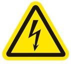
FIG 2.2.1-2 HIGH VOLTAGE WARNING LABEL
- This label is often found on shields or guards that prevent any person from coming in contact with High Voltage. This symbol may also be used on components that may carry a voltage potential that is above 50VHACPP.
Installation and Start Up
This section will describe the general installation of PowerPanelä systems. Please refer to all site-specific documentation for detailed wiring and equipment hookup instructions.
Installation of PowerPanelä Integrated Systems
Whether you are installing a full PowerPanelä or a smaller version with the PowerPanelä system, on-site preparation should have taken place prior to delivery of the equipment.
Site Template
Our engineering can send out a template to assist in placement and arranging of the conduit stub-ups prior to the concrete slab pour. This template will be site-specific, and although it is not a required item, we recommend that the template be ordered to ensure a good installation of the equipment.
If you are unsure whether or not you will receive this template, please contact our engineering staff.
Chase drawings are also available once the job has been ordered. Again, contact engineering for more information.
Equipment Delivery and Acceptance
On the day of equipment delivery, before signing off on the receipt, please make a close visual inspection of any shipping skids, banding, etc. to ensure that the equipment was not damaged in any way in transit. You should have a list of equipment provided by us to verify that all required equipment was shipped.
Any discrepancies or damage must be noted on the delivery ticket and have the driver’s initials, indicating it as having been noted.
Setting Up the Equipment
Most of the equipment we ship will be on a shipping skid that can be removed by a heavy-duty forklift. In some cases, the equipment will be delivered on an open flat-bed trailer and can be removed with the use of a crane and lifting hoist.
Once the equipment is permanently in place, the lifting bars at the top of the unit can be removed. Please refer to the “Installation Lifting Drawing” for special sealing instructions regarding the NEMA 3R design. There are seals that are included with the equipment and must be installed before unit can be approved by inspection. Proceed with the rest of the equipment installation as per the documentation. The first item to be completed is the permanent securing of the PowerPanel ä to the concrete mounting pad.
Please check all main breaker sizes, lug sizes, and feed wire sizes for compatibility before proceeding further.
Wiring Connections
Before terminating any wires to the PowerPanelä panel, perform a visual inspection of all factory wiring to look for any damage or possible loose wires.
All wires have been torqued properly at the factory. It is a good idea to go through the panel and perform spot checks of wiring by tugging on them gently to verify that there are no loose wires.
Use the documentation provided for proper wire gauge sizes and insulation types. Generally, wiring of type THHN is suited for most PowerPanelä wiring.
Cashier Control Center-Optional
If your system has a remote CCC, find a suitable location for the fuel shutdown/fuel reset station (usually mounted underneath the counter at the check stand). Verify that the fuel shutdown button will not be in an area where it will accidentally be bumped, as this will shut down all fueling operations.

FIG 1 FUELING SHUTOFF AND RESET BUTTONS
There are 4 wires from the shutdown/reset station that will be connected to the PowerPanelä.
These wires can be #16AWG or larger. It is recommended that you make the shutdown wires red and the reset wires black to avoid confusion during final termination.
The two wires connected to the shutdown button will be terminated to the lower side of terminal block ES2. You will need to remove the red jumper wire when you make this termination.
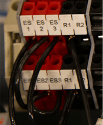
FIG 1 FUELING SHUTOFF AND RESET TERMINALS (WIRED)
Now, terminate the 2 wires from the reset button to the black terminal marked R2. The red terminal ES1 and the black terminal R1 are used for the shutdown/reset buttons on the front door of the PowerPanelä.
Once connections are made for the Fuel Shutdown/Fuel Reset station, place the cover back on the enclosure with the appropriate screws.
Remote Shutdown
For the remote shutdown pushbuttons, you will be using terminal ES3. Remove the jumper wire from this block and discard it, as it will no longer be needed.
Regardless of how many pushbuttons will be wired, they must be wired in a single series circuit.
Accidentally wiring multiple pushbuttons in parallel will result in the shutdown circuit not working properly.
Once all pushbuttons are terminated, the Fuel Shutdown/Fuel Reset circuits are complete.
Start-Up/Maintenance
This section will describe the basic steps and procedures that must be followed to ensure a safe start up when starting up the PowerPanel for the first time or restarting the system after a fuel shutdown or power outage event.
Initial Start-Up/Commissioning
The PowerPanel is a 120VAC based system. Only qualified personnel familiar with all functions of a fueling forecourt are to perform a start or restart operation.
Initial Start-Up/Commissioning Procedure
- Verify that all circuit breakers in the fueling panelboard are in the off position and verify that the ‘CP’ control breakers on the FCP-1 panel is off, as well.
- Verify that all wires are secure and that all trash from the installation has been removed. In particular, scraps of wire and/or insulation must be removed to prevent the shorting out of any components.
- After making sure all personnel are clear of the equipment, locate and turn on the circuit breaker in the panelboard labeled as E-STOP/FUEL PANEL POWER to the ON position.
- After verifying with a meter that 120V is present at terminals ‘L’ and ‘N’, turn the 10A CP breaker on the panel marked “Control Power” and turn it to the ON position.
- With a voltmeter set to VAC, measure the voltage at ES1, ES2, ES3 to neutral.
- Result: If all Fuel Shutdown pushbuttons are in the operating position, the reading of 120V should be present at all “ESx” terminals. Verify the 24VDC Power Supply is ON.
- If 120VAC is present on ES1 only, check the wiring of the Cashier Control Shutdown button and make sure that it is correct. If necessary, open the Cashier Control enclosure to troubleshoot. The bottom wire of ES2 will be landed on the shutdown button’s terminal that is furthest away from the reset button. The wire of the shutdown closest to the reset will land on the top terminal of ES3. If this is not the case, please check all ground and neutral bonding jumpers to make sure that connections are solid.
- At this point, press the RESET button on either the front door of the PowerFlow panel or the remote reset if wired in.
- Result: The ES1 & ES2 contactors should energize at this point and all STP contactors will pull in as well.
- With your meter, measure the terminals marked “2” and “N1” located at either the top right or top left of the panel. The voltmeter reading should be 120VAC.
- Turn on the 3-pole or 2-pole breakers designated for VFC STP motors. Measure each STP contactor to verify that all phases are present for each drive.
- You can now perform line leak detection, if necessary, prior to powering on the dispensers.
- Turn each dispenser breaker to the ON position. Measure the voltage at the dispenser power terminals after each breaker is switched.
- Verify after turning on each dispenser breaker that its associated low voltage relays, and Ethernet module are energized. (Low Voltage section).
- With the system up and running, go to each Fuel Shutdown button and simulate an emergency fuel shutdown.
- If your remote shutdown buttons are of the “Break Glass” type, carefully unscrew the cover until the button releases.
- After each time the panel shuts down, press the RESET button until all Shutdown stations have been tested.
- If your system uses a TLM that has an input/output card (Veeder Root), verify that the program will only send an output as long as the line leak detector is operational.
The initial start-up/commissioning is now complete.
Restarting System from Power Failure
In the event of a power failure, the ES1 & ES2 contactors will drop out immediately.
Restarting System Procedure
- Verify that no damage from a lightning strike or other storm-related damage has occurred.
- If all facility equipment checks out okay, press the green “RESET” button to start fueling operations again.
Shutting Down a Dispenser for Maintenance
If it is necessary to shut down a single dispenser for maintenance, please follow the lockout procedure located in chapter 3, section 2 at the end of the chapter for a safe shutdown.
- Bag the dispenser according to site protocols.
- Locate the breaker in the panelboard for that dispenser and turn it to the OFF position.
- Perform the lockout procedure.
Lockout Procedure
Electrical contractors or anyone qualified to work on the PowerPanel must be familiar with proper lockout procedures.
The breakers for this panel are capable of being locked out during maintenance operations or, if otherwise required, of being locked in the ON position.

FIG 1 TYPICAL CIRCUIT BREAKER AND BREAKER LOCKOUT/LOCKON ADAPTER
Critical or life safety loads require the power source to be locked in the ON position so there will be no accidental disruption of service.
Procedure
The following is the typical procedure for locking out a breaker.
STEP 1: Turn designated breaker to the OFF position.
STEP 2: With your thumb and forefinger, squeeze the retainer clips of the lockout together. Locate the two retainer holes just below the breaker handle.

FIG 2 – APPLYING LOCKOUT
STEP 3: Slip the retainer pins into the two holes and release.

FIG 2 STEP 3 – LOCKOUT ATTACHED
STEP 4: Now raise the tab of the lockout and push down toward the retaining clips. The body will slide down over the clips, and the lockout loop will appear near the top.
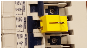
FIG 2 STEP 4 – LOCKOUT IN PLACE
STEP 5: With the lockout loop exposed, apply your padlock lock to the device. The lockout will take a lock with approximately a 5/16” shank. If you have a TAG-OUT procedure in place, apply notice at this time.
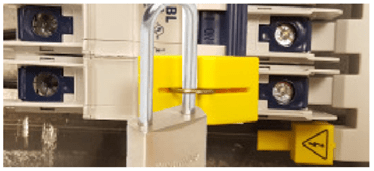
FIG 2 STEP 5 – BREAKER LOCKED OUT
If you are unsure or have questions regarding this or any other procedure described in this manual, please contact your local representative.
Other Lockouts
The main breaker that feeds power to the PowerPanel will need to be locked out if servicing of the panel itself is required.
Consult the breaker manufacturer’s procedure to perform the lockout.
If you have the optional STP breaker and bus assembly as part of your unit, use the lockout procedure as listed in 2.3. The lockouts will be different since they are made to accommodate 2 or 3 pole breakers.
Again, with this optional assembly there will be a separate feed breaker powering the bus assembly. Consult the manufacturer’s recommendations in regard to the proper method for locking out the breaker.
Maintenance
The PowerPanel needs very little maintenance to keep it in good working order.
Monthly:
- Perform an Emergency Fuel Shutdown and Reset operation and verify proper operation. If you have more than one shutdown, make sure each shutdown will turn the system to the off position.
- Open the Fueling Panel section and inner door. Visually inspect the operational lights on the TVSS to verify that it is in operational mode.
- For NEMA 3R enclosures, verify that the 3-point door latches are adjusted properly. When adjusted properly, the enclosure door will compress about half of the door gasket all the way around.
Semi-Annually:
- Inspect all door gaskets for any damage and if found, replace immediately.
- Inspect interior of cabinets (Both LV Section & Fuel Panel sections) for any buildup of moisture or other aggregates. Clean as required.
- Check the incoming voltage at the panelboard main breaker for all 3 phases and neutral.
Annually:
- Power down the main breaker of the panelboard and go through the wiring connections to verify that all is tightened as should be. Perform random ‘pull’ tests on some of the wiring to verify that no loose wiring exists.

Leave a comment